
Wiring Diagram Automotive Alternator
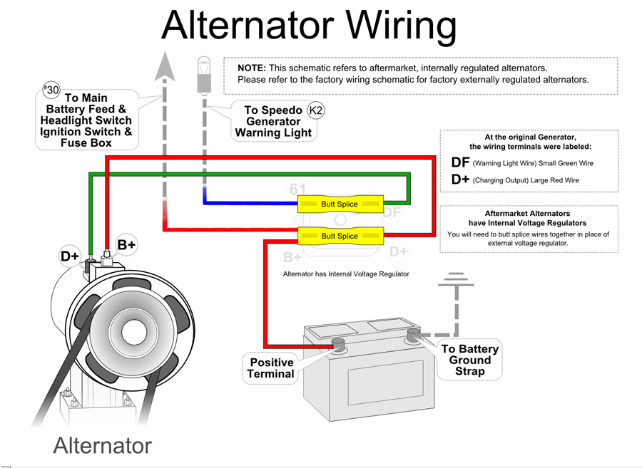
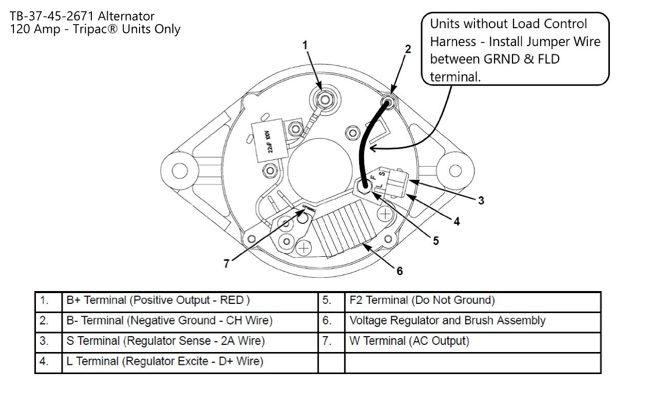
Four wires connect the alternator to the rest of the charging system. B is the alternator output wire that supplies current to the battery. IG is the ignition input that turns on the alternator/regulator assembly. S is used by the regulator to monitor charging voltage at the battery. L is the wire the regulator uses to ground the charge warning.
33 Cs130d Alternator Wiring Diagram Wiring Diagram Info
A typical 3-wire alternator wiring diagram with an internal voltage regulator. Computer-Controlled Voltage Regulation. Many late-model vehicles use the engine computer, which is often referred to as the powertrain control module (PCM), to control alternator output. Most modules use an internal driver to turn the alternator's field circuit on.
Wiring Diagram Alternator To Battery Wiring Diagram
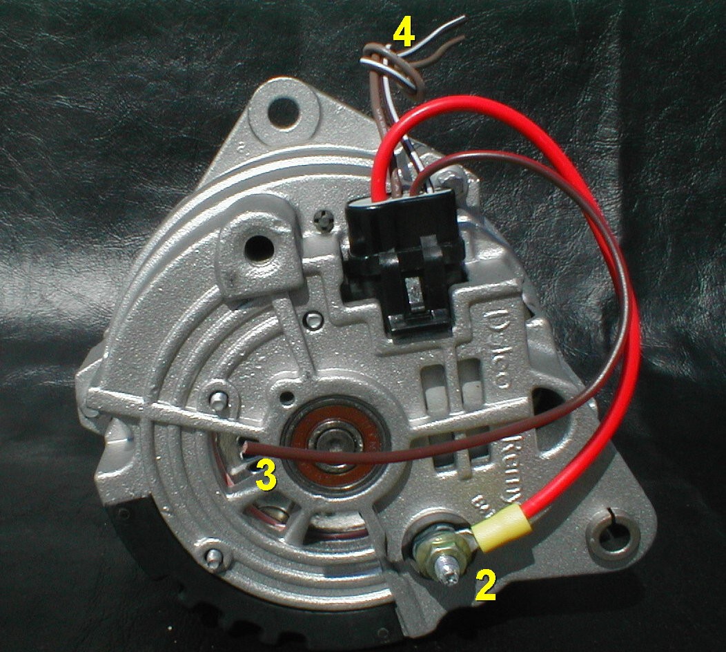
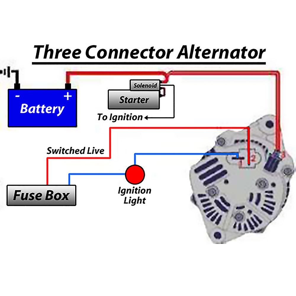
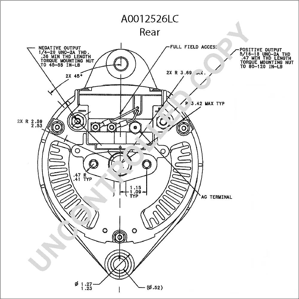
So if your alternator housing is unmarked, look from the rear of the alternator: the #1 terminal is on the left and the #2 on the right. You only need an ignition wire to the #1 terminal to make an Si series alternator work. The #2 terminal is for voltage sensing, and is optional. The #2 voltage sensing terminal allows the voltage regulator to.

Nikko Alternator Wiring Diagram
The three-wire alternator wiring diagram is a multi-purpose alternator that has built-in voltage rectifiers for power sensing, ensuring regulated voltage for all components. The external electromechanical voltage regulator involves coiling the voltage sensing cable into an electromagnet and attracts the ferrous block towards itself.

Lucas 18 Acr Alternator Wiring Diagram
Step #1 Disconnect the battery! Always do this step! Step #2 Locate the voltage regulator, usually on the firewall. Remove the ARM and FLD wires and tape them back with electrical tape in case you or the next guy want to re-install a generator. These wires connect to the generator and you don't need them. Step #3 Remove the 2 wires from the.
Circuit Diagram Of An Alternator
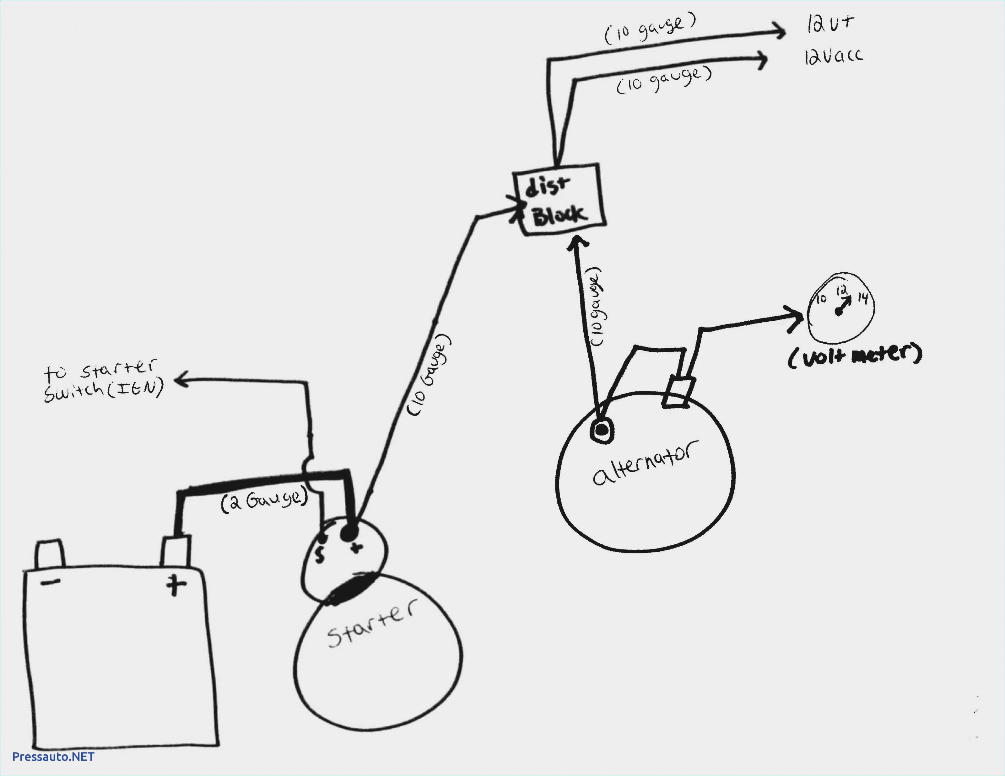
3 Wire Alternator Wiring Diagram. This is a three-wire alternating wiring diagram showing the connections between the different components of a circuit. The circuit comprises three main wires: battery positive cable, voltage sensing wire, and ignition wire. The ignition input wire is attached to the engine.

Everything You Need To Know About Alternator Wiring Diagrams WIREGRAM
Need Help? Ask a mechanic online, 24 hours a day here: https://tinyurl.com/24-7-mechanicIn this video we'll talk about a 3 wire alternator wiring diagram, ho.
Wiring Diagram 1 Wire Alternator Wiring Diagram and Schematics
Wiring an alternator warning light is fairly straightforward, and the procedure is the same regardless of the car or truck you're working on. In this article, we'll discuss the basics of wiring an alternator… Read More ». Types of Wiring Diagrams When it comes to wiring diagrams, there are two main types: schematic diagrams and.
Lucas 3 Wire Alternator Wiring Diagram For Your Needs
Hey Guys ! Today, i will be sharing some basic info about the terminal connections of an alternator with full explanation about its working of it field (rot.

Alternator Wiring Diagram 2 Wire
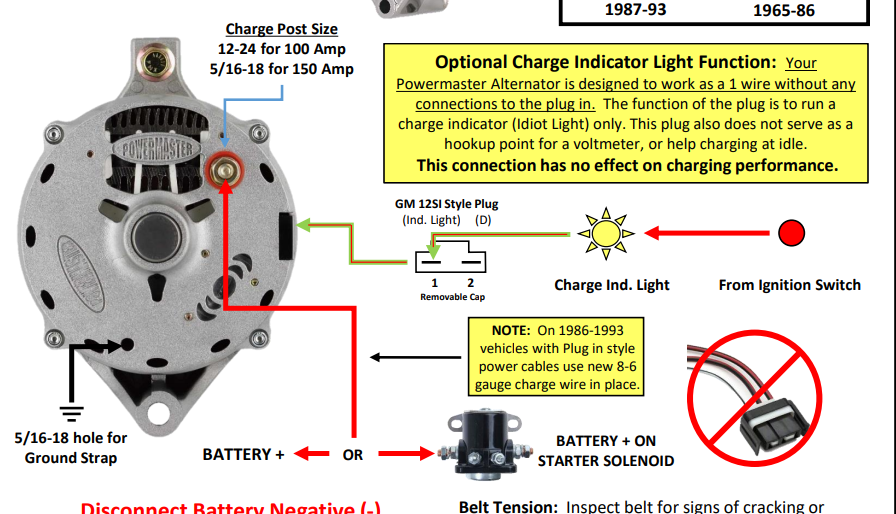
5. Connect the W Terminal. The W terminal is used for the alternator warning light or gauge. Connect this terminal to the warning light or gauge for proper monitoring of the alternator's performance. 6. Connect the Ground Terminal. Lastly, connect the ground terminal to a suitable ground point on the vehicle's chassis.
Wiring A Alternator To Battery
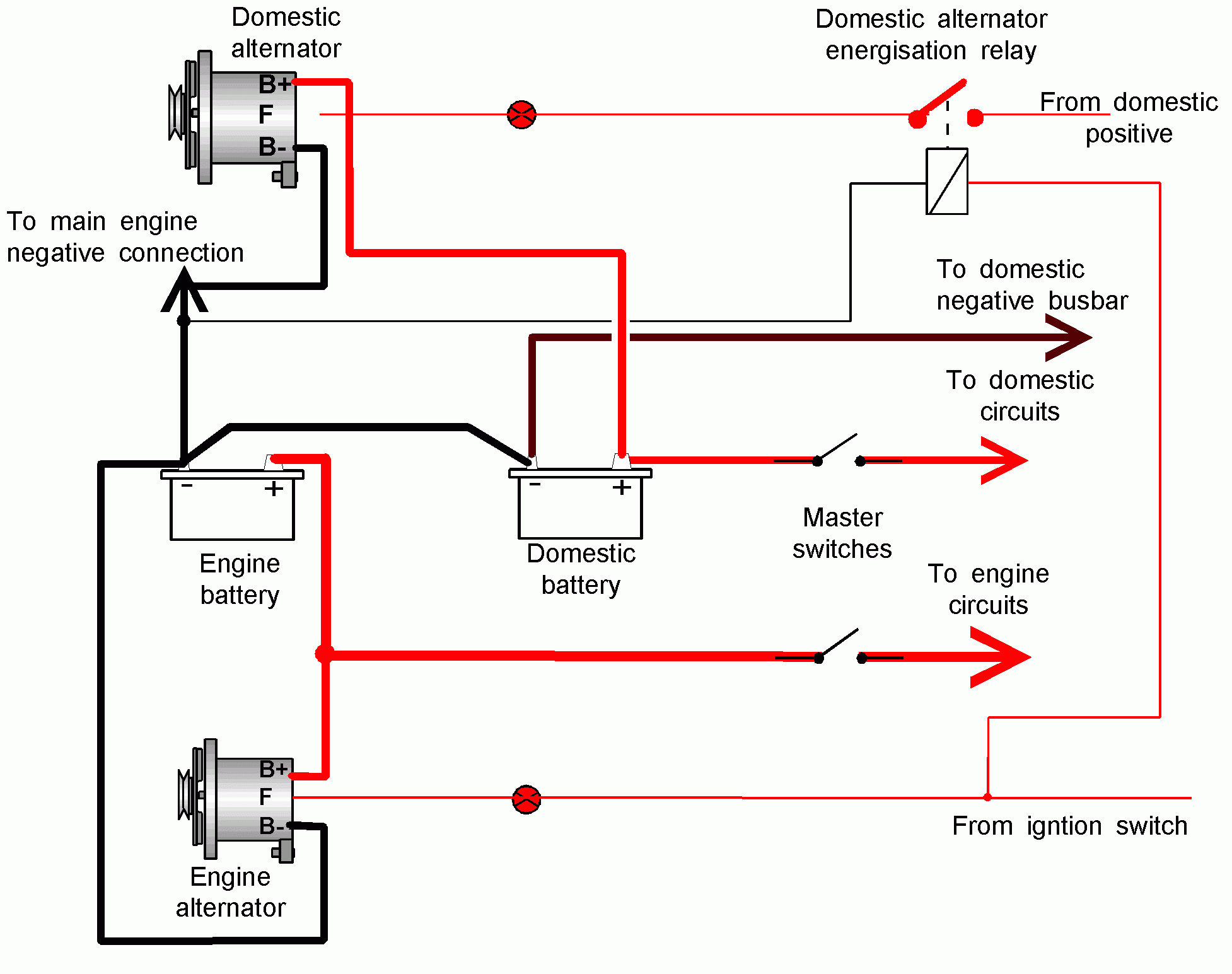
2 wire alternator wiring diagram. A 2-wire alternator has three connections, the first being the ground. This connection is also called the output connection. It allows power to flow through the alternator and other components of your car. The second connection is the positive (possibly fuseable) terminal and is connected directly to the battery.

Wiring Diagram Balmar 6 Series AlternatorElectronic DesignSchematic Circuit Power Diagram
In a 3-wire alternator, the additional fourth wire is for detecting voltage in the ignition system. Some alternators are marked with letters. If the alternator is marked with 'F' (field) and 'R' (reference/sense), then connect 'F' on the alternator to '1' on the regulator, and 'R' to '2'. If you see one marked with 'S.

Technical Understanding alternator wiring The H.A.M.B.
4 Wire Alternator Wiring Diagram is the linchpin of a vehicle's electrical system, seamlessly connecting components from the GM to Delco. It ensures an efficient conversion of alternating current from the alternator to direct current for your battery, harmonizing the electrical demands of any car, whether Ford or Chevrolet.
Leece Neville Alternators Wiring Diagram Wiring Diagram
What Are The 4 Wires On An Alternator. An alternator has four wires: the main positive wire, the primary negative wire, the sense wire, and the field wire. These wires provide power to the alternator and help regulate its output. The functions of these wires are as below.
thermo king apu alternator wiring diagram
3 Wire Alternator Wiring Diagram. This three-wire alternating wiring schematic demonstrates the connections between the various circuit parts. The three main wires that make up the circuit are the battery's positive cable, voltage sensor, and ignition input wire. There is also a connection between the engine and the ignition input wire.
Gm Single Wire Alternator Wiring Diagram
The wiring diagram for a Wilson alternator is essential for any vehicle owner who plans to install or repair an alternator. Alternators are among the most complicated parts of a vehicle's electrical system, and it's important to know exactly how they work in order to get the job done right. But knowing how to read a wiring diagram isn't easy.